Optoelectronic Hybird Integration | E-mail:sales1@cqwiseworld.com
Views: 0 Author: Site Editor Publish Time: 2026-08-23 Origin: Site
Network architects and system integrators face a demanding challenge in modern optical infrastructure. You must select components guaranteeing signal integrity over long distances and high data rates. Doing this without inflating the overall power budget requires careful consideration. Standard multi-mode lasers often struggle to maintain required stability across expanding fiber networks.
The Distributed Feedback (DFB) laser has emerged as the definitive industry standard for high-speed, single-mode optical communications. It provides unparalleled wavelength stability and spectral purity compared to legacy technologies. Engineering teams rely on these advanced lasers to scale network capacity reliably.
This article unpacks the internal mechanics of a DFB laser. We aim to help procurement and engineering teams confidently evaluate complex specifications. You will learn how to accurately match specific transmitter types to your network architectures. Finally, we will guide you through proven strategies to mitigate long-term deployment risks.
Single-Mode Stability: DFB lasers utilize a built-in Bragg grating to suppress secondary wavelengths, eliminating the chromatic dispersion penalties that limit standard Fabry-Perot (FP) lasers.
Application Specificity: Cooled DWDM modules are strictly required for dense, long-haul networks, while uncooled CWDM variants offer cost-efficiency for intermediate metro and access links.
Integration Readiness: High-power Continuous Wave (CW) DFB models are increasingly critical as external light sources (ELS) for Silicon Photonics and advanced coherent transmission.
Thermal Sensitivity: DFB wavelengths shift linearly with temperature; evaluating a vendor's Thermo-Electric Cooler (TEC) and packaging design is as critical as the laser chip itself.
Network architects need hardware built for absolute reliability. To achieve this, you must understand the laser chip itself. Standard lasers suffer from modal dispersion. They emit light across a wide spectrum. This broad spectrum ruins data integrity over long distances. The Distributed Feedback (DFB) laser solves this fundamental problem. The core innovation relies on a built-in Bragg grating mechanism.
Engineers embed a periodic grating structure directly into the semiconductor material. This corrugation sits adjacent to the active light-emitting layer. It functions as a highly selective optical filter. It dictates exactly how light travels inside the internal cavity.
Let us examine Single Longitudinal Mode (SLM) operation. Standard Fabry-Perot (FP) lasers allow multiple wavelengths to resonate simultaneously. The Bragg grating prevents this chaotic behavior entirely. It permits only one specific wavelength to reach the lasing threshold. The internal grating aggressively suppresses all secondary side modes. SLM operation forms the absolute bedrock of modern optical networking.
Why does SLM matter for your business outcomes? It directly minimizes the spectral width of your optical signal. A narrow spectral width virtually eliminates chromatic dispersion over single-mode fiber. Dispersed light pulses spread out and overlap as they travel. Overlapping pulses cause high bit-error rates. By removing dispersion, an Optical Transmitter maintains perfectly crisp signal edges. This precision enables reliable 10G, 25G, and 100G+ data transmission. You can confidently deploy these modules over distances spanning 10km to 40km or more. Standard FP lasers or VCSELs fail completely under these exact same conditions.
Modern networks require diverse wavelength multiplexing strategies. No single architecture fits every deployment scenario. You must match the transmitter type directly to your exact capacity and environmental needs.
First, consider the CWDM DFB Laser Optical Transmitter. Coarse Wavelength Division Multiplexing offers a highly cost-optimized solution. It excels in mid-range networks requiring multi-channel capacity. Engineers frequently deploy CWDM modules in 5G fronthaul architectures. They also dominate modern enterprise datacenter interconnects.
CWDM systems utilize a generous channel spacing of 20nm. This wide spacing provides a massive engineering advantage. It allows for completely uncooled operation. Uncooled lasers drastically reduce overall power consumption. They also shrink the physical module footprint. This makes CWDM ideal for high-density switch faceplates encountering heat dissipation challenges.
Long-haul networks demand entirely different capabilities. High-capacity routes rely on the DWDM DFB Laser Optical Transmitter. We frame this as the critical backbone solution for metro-core and long-haul networks. Dense Wavelength Division Multiplexing packs dozens of channels onto a single fiber pair.
These dense channels operate within a rigid 0.8nm or 0.4nm ITU-T grid. Maintaining this exact wavelength requires active thermal management. DWDM transmitters integrate a Thermo-Electric Cooler (TEC). The TEC physically heats or cools the laser diode. It maintains strict wavelength stability regardless of external conditions. This precise control prevents catastrophic adjacent channel crosstalk.
Feature | CWDM Architecture | DWDM Architecture |
|---|---|---|
Channel Spacing | 20 nm (Wide spacing) | 0.8 nm or 0.4 nm (Dense spacing) |
Thermal Management | Uncooled (No TEC required) | Active Cooling (Integrated TEC required) |
Power Consumption | Low | High (Due to active TEC) |
Primary Use Cases | 5G Fronthaul, Enterprise Interconnects | Long-Haul Backbone, Metro-Core |
Optical network speeds continue to climb exponentially. This growth drives a massive industry shift toward Continuous Wave (CW) laser architectures. We must carefully distinguish between direct and external modulation.
Legacy systems rely on direct modulation. The system turns the DFB laser current on and off rapidly. This creates the optical ones and zeros. However, direct modulation suffers from inherent bandwidth limitations. It introduces optical chirp, distorting the signal at higher bit rates.
Advanced networks overcome this limitation by utilizing external modulation. In this modern design, a High-Power DFB CW Laser Optical Transmitter serves as a steady light engine. It emits a constant, unbroken beam of high-intensity light. External components, such as Mach-Zehnder or Electro-Absorption modulators, handle the actual data encoding. They chop the continuous light beam into discrete data pulses. This clean separation maximizes signal clarity and pushes transmission speeds beyond 400G.
You must evaluate these high-power modules carefully. They perform critical roles in emerging Silicon Photonics (SiPh) transceivers. They also serve as the primary optical engine for advanced LiDAR systems and precision sensing applications.
Procurement teams should focus on three primary buyer criteria when evaluating CW architectures:
Optical Coupling Efficiency: You must measure how effectively the module channels light into single-mode fibers. Poor coupling wastes expensive optical power.
Wall-Plug Efficiency (WPE): You must calculate the exact ratio of optical output power to electrical input power. High WPE minimizes system heat generation.
Thermal Endurance: You must demand proof of sustained power output. The laser must deliver peak power without thermal degradation over its operational lifespan.
System integration requires strict adherence to technical specifications. Procurement teams cannot simply trust basic marketing brochures. You must dive into the specific optical parameters ensuring system interoperability. Let us review the foundational evaluation metrics for commercial deployments.
First, you must examine the Side-Mode Suppression Ratio (SMSR). The SMSR measures the power difference between the primary emission peak and the strongest side mode. We establish >40dB as the standard baseline for any commercial-grade DFB transmitter. A high SMSR guarantees absolute signal purity. It ensures secondary wavelengths do not cause interference.
Next, carefully analyze the Relative Intensity Noise (RIN) specification. Spontaneous emissions within the laser cavity create unwanted power fluctuations. We call these rapid fluctuations RIN. You need extremely low RIN to maintain high Signal-to-Noise Ratios (SNR). Maintaining high SNR becomes absolutely critical for advanced modulation formats like PAM4. PAM4 utilizes multiple amplitude levels, making it highly sensitive to noise.
Spectral Linewidth also requires thorough evaluation. Direct modulation naturally broadens the laser spectral linewidth. Conversely, long-reach and coherent optical systems require exceptionally narrow linewidths. A narrow linewidth mitigates phase noise across thousands of kilometers of fiber. It enables the complex phase-shift keying schemes utilized in coherent transmission.
Finally, always verify Compliance and MSA Standards. Multi-Source Agreement (MSA) compliance dictates physical dimensions and electrical interfaces. It guarantees interoperability across different vendor ecosystems. Insist on standardized form factors like SFP+, QSFP28, or QSFP-DD. This standardization ensures your new optical modules will integrate flawlessly into existing hardware.
Specification Metric | Target Value / Standard | Network Impact |
|---|---|---|
SMSR | >40 dB | Ensures single-mode purity and prevents side-mode interference. |
RIN | Very Low (e.g., <-140 dB/Hz) | Maximizes SNR, critical for advanced PAM4 modulation. |
Spectral Linewidth | Narrow (Application specific) | Reduces phase noise for coherent long-reach transmission. |
MSA Compliance | SFP+, QSFP28, etc. | Guarantees seamless hardware interoperability. |
Field deployments introduce harsh physical realities. You must proactively manage environmental variables to ensure long-term network uptime. Failing to account for these risks often leads to premature component failure.
Below are the most critical risks to evaluate before deployment:
Thermal Drifting: DFB wavelengths shift physically as ambient temperatures change. The emission wavelength drifts approximately 0.1 nm/°C. You must audit vendor datasheets for TEC reliability. Always check the specified operating temperature boundaries. Compare Commercial temperature ratings (0°C to 70°C) against Industrial ratings (-40°C to 85°C). Industrial deployments require far more robust thermal management protocols.
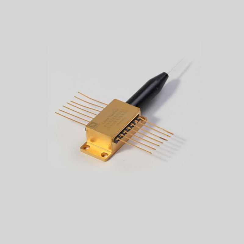
Optical Feedback Vulnerabilities: DFB lasers remain highly sensitive to back-reflections from connectors or splices. Reflected light re-enters the active laser cavity and destabilizes single-mode operation. This phenomenon causes erratic mode hopping. Integrated optical isolators solve this problem entirely. Look for isolators built directly into the transmitter package. Modules utilizing a Transmitter Optical Sub-Assembly (TOSA) or Butterfly package usually include them. We consider integrated isolators non-negotiable for all long-haul deployments.
Packaging and Yield: Evaluate packaging integrity thoroughly. You must understand the difference between hermetic and non-hermetic packaging. Hermetic seals use laser welding to block moisture completely. This protects the fragile laser chip from environmental contaminants. Non-hermetic designs cost less but degrade faster outdoors. Outside Plant (OSP) cabinets expose gear to extreme humidity and temperature swings. You must always specify hermetic packaging for these demanding field locations.
DFB lasers play a massive strategic role in modernizing optical infrastructure. They deliver the exact single-mode precision required to push data faster and further. However, selecting the right module demands a careful balancing act. You must weigh ambitious network capacity goals against rigid environmental constraints.
CWDM architectures prioritize cost-efficiency and low power consumption for mid-range links. Conversely, DWDM solutions provide the strict thermal stability necessary for dense long-haul backbone networks. Furthermore, high-power CW models open the door for next-generation silicon photonics integration.
Your next step is highly actionable. We encourage all buyers to request comprehensive vendor qualification reports before purchasing. Look beyond basic marketing brochures. Ask specifically for accelerated aging test data. Demand to see TEC power consumption curves mapped under extreme temperature boundaries. Thoroughly analyzing these documents ensures your chosen transmitters will survive real-world deployment challenges.
A: Fabry-Perot (FP) lasers emit light across multiple wavelengths simultaneously. This wide spectral width causes severe chromatic dispersion over long distances. DFB transmitters use an internal grating to produce a precise, single-mode emission. This precision eliminates dispersion penalties. It allows DFB modules to reliably transmit data across tens of kilometers, far exceeding FP limits.
A: Direct modulation struggles at speeds approaching 100G. Turning the laser current on and off rapidly introduces optical chirp and limits bandwidth. For 100G and beyond, engineers transition to external modulation. They use the DFB as a continuous light source. Separate external modulators then encode the data, maximizing high-speed signal integrity.
A: DWDM networks pack channels closely together on a rigid 0.4nm or 0.8nm grid. Transmitters must maintain extreme wavelength stability to prevent channel crosstalk. This requires an active Thermo-Electric Cooler (TEC) to constantly regulate the laser temperature. The TEC draws significant electrical current. CWDM models tolerate wider spacing and operate uncooled, saving power.