Optoelectronic Hybird Integration | E-mail:sales1@cqwiseworld.com
Views: 0 Author: Site Editor Publish Time: 2026-08-08 Origin: Site
Signal conversion dictates ultimate network survival. The optical transmitter acts as the absolute chokepoint in any RF over Fiber (RFoF) link. Here, RF signal integrity remains most vulnerable to injected noise and sudden non-linearity.
Engineers face a strict balancing act during design. You must juggle available bandwidth, transmission distance, and equipment form factor against severe signal degradation risks. Issues like laser chirp, waveform clipping, and relative intensity noise can easily ruin an otherwise perfect communication system. These unavoidable physical constraints demand careful hardware selection and rigorous testing protocols.
This article provides a robust evaluation framework for network engineers and system architects. We explore critical specifications, diverse deployment scenarios, and hidden integration risks. You will learn how to spec and shortlist the precise hardware needed for your next deployment.
Modulation type dictates performance limits; direct modulation suits cost-sensitive, lower-frequency links, while external modulation is required for high-frequency, high-linearity applications.
Laser selection (such as standard DFB vs. CWDM DFB) directly impacts scalability, channel capacity, and wavelength multiplexing capabilities.
Form factor and thermal management are inseparable; deploying mini transmitters requires strict adherence to Size, Weight, and Power (SWaP) constraints without sacrificing dynamic range.
Datasheet specs must be evaluated within the context of the total optical link budget, including receiver sensitivity and passive component insertion loss.
We must establish acceptable baseline metrics before reviewing specific hardware components. You need strict targets for signal-to-noise ratio (SNR) and carrier-to-noise ratio (CNR). End-to-end link loss directly dictates your available optical budget. Without firm success criteria, system architects risk over-engineering the link and wasting valuable rack space.
We map transmitter requirements to specific use cases early in the design phase. Distinct applications demand entirely different performance profiles.
SATCOM (L-Band, S-Band, C-Band): Satellite downlinks place a high emphasis on exceptionally low phase noise. High linearity remains critical for maintaining complex modulation schemes across long physical distances.
CATV & Broadcast: Network architects focus heavily on wideband frequency flatness. You also face stringent composite second order (CSO) and composite triple beat (CTB) distortion limits across crowded channel plans.
Distributed Antenna Systems (DAS) & GPS: These setups require extremely tight synchronization. Minimal processing latency ensures accurate timing distributions across massive cellular footprints.
Fiber distance strictly defines your total optical link budget. You calculate expected attenuation over single-mode fiber in decibels per kilometer (dB/km). Standard 1550nm fiber loses roughly 0.25 dB for every kilometer of distance traveled. You use this baseline calculation to determine the absolute required optical output power. Do not rely on casual estimates; model the exact physical path including all splices and connector losses.
Engineers must choose between two primary modulation architectures. Each approach carries distinct physical advantages and strict engineering limitations.
This mechanism operates by modulating the laser bias current directly using the incoming RF signal. It offers a straightforward approach to RF-to-optical conversion. The laser diode intensity simply rises and falls matching the applied RF voltage.
Direct modulation remains highly cost-effective and structurally simple. It utilizes fewer internal components and consumes significantly less power. However, it proves highly prone to laser chirp under dynamic loads. Bandwidth limits usually cap maximum performance around 3 to 6 GHz.
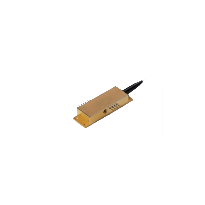
You will find optimal results utilizing a Mini Direct Modulation Optical Transmitter for compact, edge-network deployments. These units shine where equipment space remains limited and frequency bands stay moderate.
This advanced mechanism uses a continuous wave (CW) laser acting purely as a light source. It relies on an external modulator, typically a Mach-Zehnder interferometer, to encode the RF signal onto the light path.
External modulation delivers exceptional linearity across wide spectrums. It effortlessly supports high frequencies ranging from 10 GHz to beyond 40 GHz. You experience almost zero laser chirp since the laser operates at a constant intensity. Conversely, this architecture demands higher complexity, increased power consumption, and tighter thermal management.
We highly recommend deploying a Mini External Modulation Optical Transmitter Module in space-constrained avionics. They also dominate modern radar applications and high-density satellite ground stations. These environments categorically require zero-compromise signal integrity.
Core Architecture Differences
Operational Feature | Direct Modulation | External Modulation |
|---|---|---|
Primary Mechanism | Bias current variation | CW laser + External Modulator |
Practical Bandwidth Limit | Typically 3 - 6 GHz | 10 GHz up to 40+ GHz |
System Linearity | Moderate | Exceptional |
Chirp Susceptibility | High | Minimal to None |
Hardware Complexity | Low | High |
Choosing the correct optical hardware requires deep analysis of datasheet specifications. You must look past marketing claims to understand true physical limits.
System architects rely heavily on Distributed Feedback (DFB) lasers for analog transport. They provide the extremely narrow linewidth required for high-performance links. Narrow linewidths prevent chromatic dispersion from destroying the signal over long fiber runs.
You maximize existing infrastructure efficiency by integrating a CWDM DFB Laser Optical Transmitter into your core network. This specific configuration allows you to multiplex multiple distinct RF signals over a single fiber strand. Coarse Wavelength Division Multiplexing (CWDM) easily conserves highly valuable dark fiber resources.
SFDR acts as the ultimate measure of analog transmitter fidelity. You measure the functional range between the noise floor and the threshold of unacceptable third-order intermodulation distortion (IMD3). A wider SFDR guarantees clearer signal reproduction under heavy, multi-carrier traffic loads. Engineers must prioritize high SFDR values to prevent intermodulation products from burying weaker adjacent signals.
Inherent laser noise directly limits the maximum achievable SNR. We call this phenomenon Relative Intensity Noise. It proves especially critical in sensitive analog transmission. High RIN values will degrade your carrier signals long before optical fiber attenuation becomes a measurable problem. You must seek lasers featuring exceptionally low RIN profiles for wideband applications.
You must ensure the transmitter maintains a perfectly flat frequency response. It should cover your specific target band without aggressive roll-off near the upper or lower limits. Uneven frequency response introduces severe amplitude distortion across multi-carrier signals. This distortion forces receivers to work harder, ultimately raising the bit error rate in digital overlays.
Paper specifications rarely survive real-world deployment untouched. You must actively mitigate environmental and hardware integration risks.
Engineers constantly balance Size, Weight, Power, and Capital constraints. High-performance mini modules pack tremendous operational power into tiny physical footprints. However, they require rigorous heat-sinking to prevent disastrous thermal wavelength drift. Poor thermal dissipation limits dictate exactly how densely you can rack these components in server closets or remote enclosures.
Back-reflections pose a severe and constant threat to laser stability. Reflected light bounces back down the fiber and violently disrupts the internal laser cavity. You must evaluate components for built-in optical isolators. High Optical Return Loss ratings prevent these stray reflections from destroying pristine signal integrity.
A powerful transmitter can easily overdrive a highly sensitive receiver. The optical output power must never exceed the receiver photodiode damage threshold. You must execute precise optical attenuator planning during the design stage. Failing to match these ends correctly leads to severe signal clipping and harmonic distortion.
Modern remote networks demand high agility. You should heavily assess the value of digitally adjustable gain blocks. Automatic Gain Control (AGC) stabilizes optical output despite wildly fluctuating RF inputs from antennas. Remote monitoring via SNMP protocols ensures long-term operational stability and enables proactive fault detection.
Moving from technical evaluation to actual procurement requires strict vendor validation. Never assume all hardware performs identically in the field.
Never rely solely on basic off-the-shelf component specs. You must evaluate the manufacturer’s willingness to provide raw testing data. Top vendors offer custom parameter tuning and dedicated engineering integration support. They help you model the exact link behavior before you purchase.
Verify environmental certifications before making final hardware selections. You absolutely need MIL-STD compliance for rigorous defense deployments. Telecom environments strictly require NEBS compliance to ensure safety and reliability. Harsh deployment environments destroy unprotected electronics rapidly.
Glossy marketing sheets often hide fatal performance flaws. You must request detailed, unvarnished engineering data from the manufacturer.
Demand comprehensive S-parameter files for accurate system-level modeling.
Request absolute phase noise plots covering multiple frequency offsets.
Review strict temperature-dependent performance curves to verify thermal stability.
Ask for detailed IMD3 testing parameters to confirm the advertised SFDR.
Choosing an optical transmitter is never an isolated hardware decision; you must match it precisely to the RF input and the chosen optical receiver.
Decision-makers must prioritize system linearity (SFDR) and modulation appropriateness over raw optical output power.
Review your integration environments early to ensure strict SWaP constraints align perfectly with available thermal management capabilities.
Take immediate action: engage directly with vendor application engineers to comprehensively model the total optical link budget before procurement.
A: Maximum transmission distance depends heavily on optical fiber attenuation. This averages roughly 0.25 dB/km at the 1550nm wavelength. You must also factor in the laser output power and receiver sensitivity. By properly balancing these metrics, high-quality links often reach up to 100km without requiring inline optical amplification.
A: CWDM becomes strictly necessary when you need to expand channel capacity over existing fiber infrastructure. Instead of pulling new cables, CWDM allows you to transmit multiple distinct RF feeds simultaneously. Each feed rides on a separate optical wavelength, safely combined onto a single physical fiber strand.
A: If your optical link runs a very short distance, natural fiber attenuation remains low. Consequently, high transmitter output power can easily saturate or physically damage the receiving photodiode. You use an optical attenuator to pad the signal down, keeping optical power safely within the receiver's optimal dynamic range.