Optoelectronic Hybird Integration | E-mail:sales1@cqwiseworld.com
Views: 0 Author: Site Editor Publish Time: 2026-08-16 Origin: Site
Selecting the right optical transmitter represents a core engineering dilemma in modern network architecture. Engineers constantly balance strict link budgets, signal integrity, and physical footprint constraints. Both major technologies convert electrical data into optical signals. However, their internal mechanisms drastically alter dispersion tolerance, transmission reach, and thermal management. Direct modulation directly varies the laser current to embed data. External modulation relies on a continuous wave combined with a separate high-speed optical shutter.
This article provides network architects and technical teams with a clear, evidence-based evaluation framework. We will explore the exact technical trade-offs between Direct Modulation Lasers (DML) and Externally Modulated Lasers (EML). Understanding these distinct differences ensures optimal network performance. You will learn how to match each specific technology to exact deployment scenarios effectively. This prevents over-engineering and keeps your network topology streamlined and reliable.
Direct Modulation (DM): Highly cost-effective and space-efficient for shorter-reach, lower-speed applications, but limited by frequency chirp and chromatic dispersion.
External Modulation (EM): Essential for long-haul and high-capacity networks, offering superior signal quality, high extinction ratios, and low chirp, though at a higher cost and complexity.
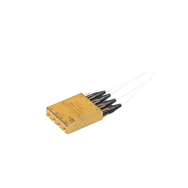
Form Factor Innovation: Advanced configurations like the multi-channel DM optical transmitter and mini external modulation optical transmitter module are blurring traditional deployment boundaries.
TCO Considerations: The decision must factor in not just component cost, but thermal management, fiber type, and long-term network scalability requirements.
Establishing a firm grasp of underlying device physics helps you make better architectural decisions. Every optical transmitter fundamentally operates as an electro-optic transducer. Yet, the method it uses to manipulate photons dictates its overall performance ceiling.
Direct modulation relies on a relatively straightforward process. The driving electrical current directly modulates the laser diode. Most modern networks utilize a Distributed Feedback (DFB) laser for this task. As the input current fluctuates between high and low states, the laser emits corresponding pulses of light.
This simplicity creates an inherent physical byproduct. Changing the drive current inherently alters the carrier density inside the laser cavity. This rapid shift changes the refractive index of the active region. The result is transient frequency chirp. The signal spectrum continuously broadens during data transmission. Over longer fiber distances, chromatic dispersion scatters these broadened signals, severely degrading network integrity.
External modulation decouples the light generation from the data encoding process. The internal laser operates strictly in a Continuous Wave (CW) mode. It outputs a steady, uninterrupted beam of light. This stable light then passes through an external modulator.
Engineers typically use a Mach-Zehnder Modulator (MZM) or an Electro-Absorption Modulator (EAM). The external device acts as an ultra-high-speed shutter. It blocks or passes the continuous light beam based on the incoming electrical data stream. This physical isolation protects the laser from transient current fluctuations. It effectively eliminates direct frequency chirp, maintaining a narrow, stable optical spectrum.
Choosing an optical transmitter requires evaluating multiple interacting variables. You must assess how each modulation type handles distance, power, and signal clarity.
The high chirp inherent in direct modulation restricts its viable transmission range. As the modulated pulses travel through standard single-mode fiber, different wavelengths travel at slightly different speeds. High chirp exacerbates this effect. The pulses eventually smear into one another.
External modulation maintains near-zero chirp. The pulses remain sharp and tightly contained. This minimal spectral broadening allows the signal to travel significantly further. You can push EML signals across vast distances before they require complex optical regeneration.
Extinction Ratio measures the power difference between a transmitted optical "1" and a "0". A higher ER indicates a clearer, more defined signal. Direct modulation naturally struggles to achieve high ER. Completely turning off the driving current causes unacceptable laser turn-on delays.
External modulators excel here. They physically absorb or redirect the light. This allows them to achieve a much higher ER. A high ER produces a pristine eye diagram. Consequently, you will see a dramatically lower Bit Error Rate (BER) at the receiving end.
Power constraints often dictate architectural choices. Direct modulation typically offers lower maximum output power. Pushing a DML too hard dramatically increases thermal instability and chirp.
In contrast, isolating the laser allows for aggressive amplification. For long-distance connections requiring massive optical force, engineers frequently deploy a High Power DFB External Modulated Laser Optical Transmitter. Such a device can drive clean, powerful signals across extensive metropolitan spans or long-haul routes without needing immediate mid-span amplification.
Physical limitations traditionally cap DML performance at lower gigabit speeds. Carrier dynamics inside the laser cavity resist ultra-high-frequency toggling. EMLs bypass these internal physics. The external electro-optic effect operates at vastly higher frequencies. External modulation remains the universally accepted standard for 100G, 400G, and emerging single-wavelength links.
Evaluation Metric | Direct Modulation (DML) | External Modulation (EML) |
|---|---|---|
Frequency Chirp | High | Very Low to Zero |
Dispersion Tolerance | Low (Requires shorter runs) | High (Suitable for long haul) |
Extinction Ratio | Moderate | Excellent |
Max Data Rate | Lower bounds (Typically up to 25G/50G) | Ultra-high (100G, 400G, 800G) |
Circuit Complexity | Simple | Complex |
Ignoring chromatic dispersion limits on fiber runs exceeding 20 kilometers.
Overlooking the thermal footprint of integrated modulators in dense faceplates.
Assuming direct modulation scales linearly to higher bit rates without severe signal degradation.
Direct modulation provides the most streamlined solution for many network topologies. When raw distance is not the primary obstacle, DMLs offer massive efficiency benefits. You should frame your business cases around footprint and complexity reduction.
You will find direct modulation heavily deployed in Data Center Interconnects (DCI). Enterprise Local Area Networks (LANs) also rely heavily on this technology. Fiber-to-the-Home (FTTH) and Passive Optical Networks (PON) utilize DMLs exclusively at the subscriber edge. Furthermore, shorter metro access links under 40 kilometers represent prime deployment zones.
DMLs boast a highly streamlined architectural footprint. They require simpler driver circuitry. They eliminate the need for a separate physical modulator block. This reduces overall power consumption per port. Consequently, you can achieve incredibly dense port configurations on a single switch faceplate. The simplified design intrinsically increases overall component yield during manufacturing.
Modern engineering has pushed DML constraints forward through clever parallelization. Space-constrained environments often demand higher aggregate bandwidth without transitioning to complex external structures. To achieve this, architects deploy a Multi-channel DM Optical Transmitter. By utilizing parallel optical lanes, such as CWDM4 architectures, you can multiplex several simpler DML streams. This bypasses the single-wavelength speed limits. It provides massive data throughput while maintaining the smaller physical footprint of direct modulation.
Certain engineering thresholds demand uncompromising signal linearity. When the optical link must span massive distances or carry extreme data loads, external modulation becomes strictly mandatory. The performance gains easily justify the added integration complexity.
Long-haul telecommunications completely depend on EMLs. Ultra-high-speed core networks cannot tolerate signal smearing. Dense Wavelength Division Multiplexing (DWDM) systems require tight channel spacing. DML chirp would cause unacceptable crosstalk in DWDM environments. Additionally, analog CATV transmission requires perfect signal linearity. Any deviation introduces distortion. External modulation guarantees this required strict linearity.
Historically, external modulators were bulky, discrete components. They consumed significant board space. Modern integrated photonics have fundamentally solved this issue. Advanced fabrication techniques combine the CW laser and the modulator onto a single chip.
This integration leads directly to the Mini External Modulation Optical Transmitter Module. Engineers can now pack high-performance EML technology into ultra-dense, pluggable transceivers. Form factors like QSFP-DD now comfortably house external modulators. You can deliver core-network performance directly at the network edge.
Passive optical networks often feature numerous optical splitters. Each splitter introduces significant insertion loss. Driving a signal through multiple split-points requires immense initial launch power. Direct modulation cannot safely generate this power without distorting the signal. Integrating an external modulator with a dedicated high-output DFB laser perfectly solves this physical limitation.
Spec-sheet promises rarely survive real-world deployment untouched. You must evaluate the implementation risks to ensure long-term network stability. Understanding physical operating environments proves just as vital as understanding optical physics.
All laser diodes react poorly to temperature fluctuations. A shifting temperature alters the optical cavity length. This changes the output wavelength. Direct modulation lasers prove especially sensitive to this thermal drift. They often require precise Thermo-Electric Cooling (TEC).
External modulators generate additional ambient heat. The required bias voltage across the modulator creates thermal waste. However, because the EML laser runs at a constant current, its base operation remains highly stable. You must evaluate your available rack cooling infrastructure before deploying high-density EMLs.
Always provision adequate airflow around EM transceiver cages.
Monitor ambient rack temperatures continuously using automated telemetry.
Implement intelligent TEC control algorithms to prevent condensation.
Adding components increases the mathematical probability of failure. External modulators inherently add an internal point of optical insertion loss. The light must physically pass through an extra medium. Furthermore, it complicates the driver circuitry.
You must calculate the Mean Time Between Failures (MTBF). A highly integrated, simpler DM setup generally boasts a superior MTBF purely due to its lower component count. You must weigh this raw reliability against the performance benefits of a complex EM assembly.
Under-specifying an optical transmitter presents severe long-term risks. Choosing direct modulation purely for immediate simplicity might constrain your architecture. If network data rates upgrade drastically within the next three years, DML links might hit a hard physical wall. You could face a highly disruptive "rip and replace" scenario. Always analyze your long-term bandwidth roadmaps. Over-provisioning distance and speed capabilities today often prevents massive architectural overhauls tomorrow.
The engineering choice between direct and external modulation requires a strict, objective calculation. You must constantly weigh distance, data rate, and dispersion limits against your available footprint and thermal constraints. Direct modulation shines in high-density, short-reach access layers. External modulation dominates when absolute signal integrity over massive distances remains non-negotiable.
Moving forward, we recommend the following action-oriented steps for your procurement and engineering teams:
Map out your maximum exact link distance requirements before reviewing transceivers.
Calculate your absolute worst-case optical loss budget, factoring in all passive splices and splitters.
Define your thermal dissipation limits per rack unit to avoid module overheating.
Project your required per-wavelength data rates for the next five years.
Avoid finalizing architecture plans in a vacuum. We strongly encourage you to consult with a specialized technical engineering team. Request a detailed demonstration or a highly specific performance spec sheet. Matching the exact transmitter architecture to your unique network topology guarantees operational stability.
A: Technically yes, but only for exceptionally short reaches. However, dense channel spacing poses a major architectural risk. The high frequency chirp inherent in direct modulation causes spectral broadening. This inevitably leads to severe crosstalk between adjacent DWDM channels. External modulation remains the strict, universally accepted standard for DWDM.
A: Yes, it generally draws slightly more overall power. The external modulator component requires a constant electrical bias voltage to function as a shutter. However, modern photonic integration has drastically reduced this power gap. They are much more efficient today compared to legacy, discrete EML designs.
A: High-chirp signals degrade rapidly over long optical distances. This degradation forces engineers to deploy highly sensitive, advanced receivers. Alternatively, you must insert specialized dispersion compensation modules along the fiber link. This added receiver complexity often negates the initial hardware simplicity gained from using a direct modulation transmitter.